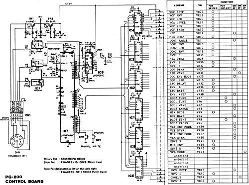
Schematic detail PG-800 (Copyright Roland)
Introduction:
Sound editing on synthesizers is not every one's cup of tea. Endless tweaking of parameters and trying.
On Roland synthesizers the sound parameters can be found in elaborate menus.
As an option the Roland company introduced a nifty feature for their products. Little controller boards that allow quick and direct programming of all parameters through sliders, knobs and buttons.
There are several versions of these controller boards, depending on the complexity of the synthesizers.
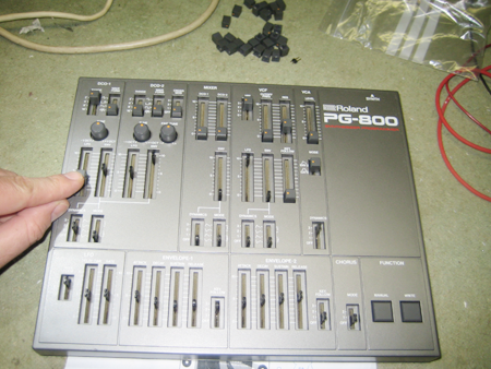
A very popular Roland synth is the JX-8p keyboard and it has a keyboard less rack version, the MKS-70. The controller to these synthesizers is the PG-800.
I received a broken PG-800 for fixing the other day; with a working MKS-70 for testing. It's repair turned into a nice little project replacing the original parts. Here's a story of my findings. It's a bit technical, but the summary will give short details of what can be done to revive your unit.
Background description of the PG-800:
As a reference it's a good idea to first start to have a copy of the Roland Service Manual at hand. I had to rely on a very good scan of the original which i found on the excellent analog hell website.
Schematic detail PG-800 (Copyright Roland)
The schematics are very easy to read. From right to left: A lot of potmeters, analog channel selector, single A/D converter, two push buttons and a microcontroller, buffers to the synthesizer connector. And a supply and reference voltage section.
The potentiometers
|
There are two types of slider potmeters with 30mm and 15mm travel. All have a 100 kOhm value and the long are used for continuous parameters, while the short ones have little dentented steps as to create six positions. These are used as pseudo switches; the values are not discrete contact closures as usual, but rather six resistor divider values. Depending on how many actual steps are needed, the top cover slits limit the travel range of the potmeters and in this way 2-, 3-, and 4 position switches are made. All the potmeters receive a fixed reference voltage of (about) 2.5V from a central supply on the top end. The low ends are connected to ground; 0V. The runners of the potmeters therefore produce a voltage value between 0 and 2.5V. Little care should be taken with the pseudo switch sliders. Sometimes the first position is at ground level, sometimes it's at a step higher. But as this is always the same for a specific control one can make a table of this behaviour and correct for it on every reading. There are a total of 44 slider potmeters; 44 parameters to control no less! | 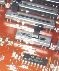 Long, short slider and 4051 in foreground. |
Analog selectors; HD14051BP
The analog multiplexers or selectors are like switchboards. A number of digital lines select a channel and the analog voltage level of only one potmeter at a time. In the PG-800 6 of the very popular 4051 series CMOS switches are used. As can be seen in the picture they are here called HD14051BP; it's the naming of Hitachi of this popular component, which is made by dozens of manufacturers. They all have the root naming of '4051; in common. Information of these is widely available; just try 'CD4051' in Google. CD4051 is the naming of the original manufacturer RCA.
The 4051's each are capable of selecting one-out-of-eight signals. Next to that the ICs have enable lines (or INHIBIT as they are called) that allows the selection of a single IC; when inhibited the output is left floating and other chips can set the voltage.
With six units a total of 48 lines could be accomodated, but four are not used and are tied to the +5V supply.
The selector lines are controlled by the microprocessor. The analog outputs are all knotted together and lead to the single input of the A/D converter.
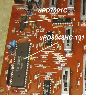
The uPD7001C A-to-D converter.
The A-to-D converter takes care of making the analog signals digital. While the potmeters can produce any voltage, the converter, in this case an 8 bit one, limits the outcome to two-to-the-power-of-eight (2^8) = 256 possible values. It's like dividing the potmeters into 256 little regions with a unique ZIP code.
The A/D converter also listens to ground and the 2.5V reference voltage, so it always knows what the minmum and maximum ZIP codes are. When the converter has determined the ZIP code it tells this to the microcontroller by changing a EOC (end-of-conversion) line. The microcontroller then toggles a SCK (clock) line; a bit like saying 'tell me the next digit in the ZIP code'. The converter tells this through a SO (serial out) line; one by one, on the clocks.
The uPD7001C has a 4 channel multiplexer on the input. In the PG-800 this feature is not used. The addressing lines are all tied to fixed level so only one input is used.
Datasheets on the uPD7001C can be found searching the web. The uPD7001C was only made by NEC and safe to assume they are no longer in production, they are hard to find.
Added note: Looking at the sequence of readings with the original processor i found that all 48 channels were scanned. It is odd that also the 4 un-used inputs that are tied to +5V are scanned as that is out of range for the A/D converter. The datasheet for the uPD7001C tells that there is no problem going above the 2.5V reference, but that the output value will always read maximum.
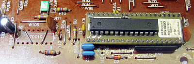
The uPD8048HC-191 microcontroller.
The 8048 line of microcontrollers is very popular. Again there are many manufacturers; they were first introduced by the Intel corporation. Later several companies made compatible derivatives or got a licence to produce the 8048.
In general a microcontroller is a microprocessor with on-board program and data memory and other features. It's perfect for an application like the PG-800.
Microcontrollers have a program fixed inside that is very specific for the application. In the PG-800 application this amounts to: Selects an appropiate analog channel, asks the A/D converter what the set level of the attached potmeter is, sniffs the keys if they are pressed. Then it keeps a little table of historic values and only if one has changed it stores that as the new position and only when changed tells the synthesizer about it.
The 8048 in the PG-800 has a '-191' suffix printed on it. A 8048 with Hitachi program '191' loaded inside; these were made specially by Hitachi for the PG-800. The program was hardware coded on the chip level.
Rob Senso of the life saver web shop 'Vintage Planet' told me they are really really hard to find.
The DTA114 output- and DTC input transistors.
The DTA114 and DTC114 seem to be specifically designed as digital line buffers. It is important to notice they also invert the logic levels of the signals.
In the application in the PG-800 the 8048 is probably not capable of driving the signal lines directly, so these transistors buffer the signals.
The DTA114 and DTC114 are general purpose devices, but they are not an industry standard. In a quick search i've not been able to find a supplier.
Initial repair efforts:
|
On arrival a quick probing with the osciloscope revealed that the READY OUT line, telling the synth there was a new change, was never actuated when sliders or switches were operated. Also there was no activity on the A/D converter or the 4051's. Obvious first though: the 8048 has failed. Looking a bit further though.. the A/D converter should be operating on it's own accord. It has an internal cycle timer and whenever it has calculated a new conversion it should operate it's end-of-conversion like crazy; there's no way of stopping this. In fact, the end-of-conversion was never actuated.. dead A/D. When manually triggering the line by connecting it with a wire to ground momentarily: The microcontroller came to live shortly! Different 4051 port, message to synth.. that looked good! OK, so what to do. Looking at the A/D converter it struck me as rather simple. Mind you, simple with todays technology; it was top brass at it's time! |
|
Processor and A/D replacement
Replacing the uPD7001C with a microcontroller.
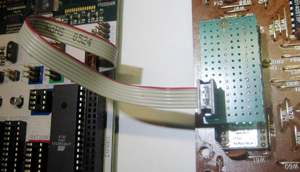
I decided to do a makeshift replacement of the uPD7001C with a modern Atmel microcontroller that has onboard A/D conversion. This way i would be able to test if the rest of the PG-800 was fully functional.
Atmel ATmega168 replacing the uPD7001C
Once set up, the MKS-70 responded well to all the controls again. With this solution the PG-800 could be fixed. But as can be seen in the picture there is very little room to put in the microcontroller.
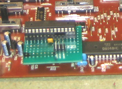
Replacing the uPD8048HC-191 microcontroller and uPD7001C.
Next step was to start thinking about replacing the original 8048 as well. The larger DIL40 footprint space would fit a converter PCB with the new Atmel processor.
Now it's not easy to actually read the program in the original 8048.
But we do now have a working system and it is possible to measure what the 8048 is doing.
Oscilloscope again. That was a bit difficult as the signals only light up very shortly on my old osciloscope and then dissapear again. In modern oscilloscopes the image can be frozen when something happens. But with a bit of patience and a digital camera i took some hundred images of the scope screen and sifting through those i could see what everything did.
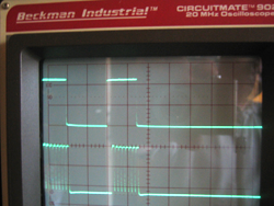
Here's a nice picture: READY OUT on top, CLOCK IN bottom. All measured on the PG-800 connector.
What happens is that all the potmeter values are sampled in sequence and continously. There is a test pin near the 8048 that generates sync signals on the start of every sequence. Looking at the input of the A/D converter one can see a train of analog values, each corresponding to a control potmeter.
The signals to the synthesizer remain quiet as long there is no change of any parameter. If a parameter is changed then two bytes are sent to the synthesizer. This is done via synchronous serial data at about 9600 bits per second. The READY and CLOCK IN are positive logic and the 'DATA OUT' (not shown here) is negative logic.
The synchronous data transfer works as follows: At the start of a new byte, the PG-800 raises the READY line. The synth responds with eight clock pulses. On each of the eight clock pulses going high, the PG-800 shifts out the next databit of the byte, which the synth probably latches on the negative going clock. The byte is sent with the most significant bit (MSB) first. This was all just a bit of trial and error finding out.
On a side note: Please be aware that while testing the clocks must be produced going toward the PG-800. If it doesn't receive clocks for the data, the PG-800 freezes up completely. Also the channel scanning stops. So you can't really test the PG-800 without the JX-8p or MKS-70 being connected.
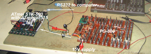
Now, knowing the form of communication, i built a second microcontroller circuit on the Atmel STK-500 to mimic the synthesizer. All the codes generated by the PG-800 where then sent via a regular RS-232 to my PC so i could see what the codes were.
Eavesdropping on the PG-800..
I found two bytes on each change form a message. Exceptions are with operating the switches. I've compiled a list of all the codes, which you can download here as PDF.
The original schematic has a great table indicating how the parameters are to be addressed through the analog multiplexers.
Now we have all the details for writing a program for the new processor. It took some testing an trying, but finally everything seemed to work.
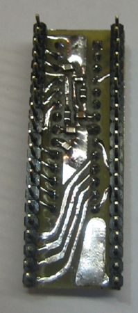
I also made a little adapter PCB so the new processor would fit in place of the 8048. It contains the processor and some SMD components. These are mainly to condition the power and to provide some filtering on Vref and the common analog signal from the multiplexers.
The end result was a prototype first, and later a slightly modified final version. The final version features the ATmega48P-20PU. It's a little brother of the ATmega168 i used during testing. It has less code space and memory, but by far enough for this application.
The final version can be seen here:
 |
 |
Power supply
Attention should be given to the 5V supply. The original circuit with TR1 produced a voltage of 5.35V when i first tested the PG-800. The current drawn was about 70mA.
With the replacement processor the current draw is only 18mA; the new processor uses far less energy. But as a result the supply went to 5.45V. The new processor is allowed to run up to 5.5V, but i found it a bit too close for comfort.
I replaced the original TR1 with a regular 7805 voltage regulator. One only needs to remove R1, cut two traces and add two wires. Now it's running at a safe 5.05V.
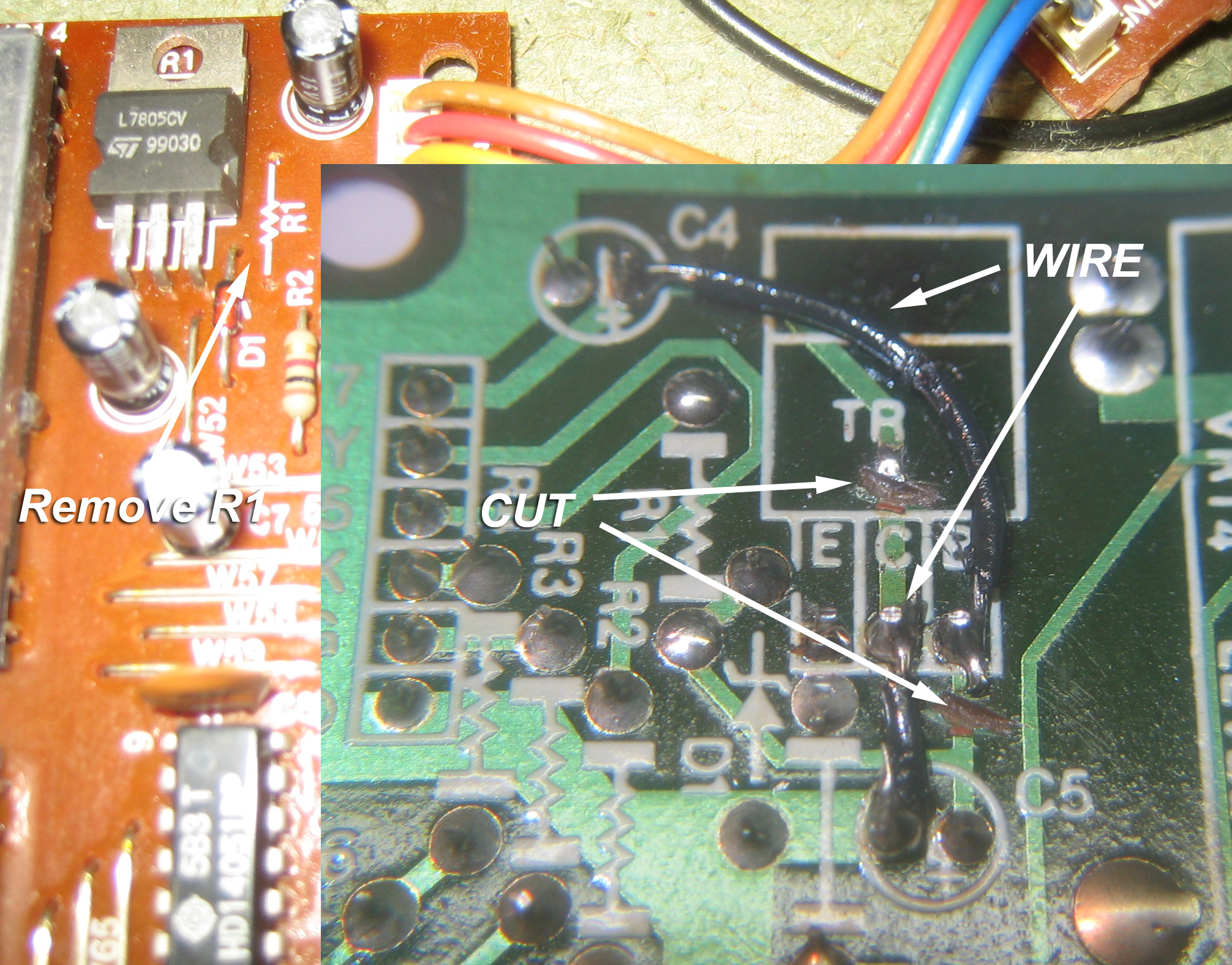
Replacing TR1 with an 7805.
Extra features
-Transistor bridging
An added feature was made so all the DTA and the DTC transistors can be removed should one or more fail. The Atmel ports are strong enough to drive the lines directly. I've fully tested this feature.
First all the transistors are removed and three wire bridges should be installed as can be seen in the photo. Also remove resistors R6, R7 and R8. Also install a jump wire on the position of the reset capacitor C11 near the processor. The new processor detects the wire jumper and then reverses the logic state on the data, clock and ready line.
![]()
Click for large image.
-In circuit programmable
With the new processor, as an added bonus, it remains possible to reprogram at any time. Just apply power to the PG-800 and with a little clamp-on converter board the Atmel can be programmed via SPI!
This is very useful if features need to be changed or added... he, he.. i'm already thinking of adding a MIDI OUT to the PG-800. Then all slider movements could be directly recorded to a DAW! ;)
Summary
This replacement will revamp your Roland PG-800 in case the uPD8048-191 processor or the uPD7001C A/D converter have failed. This mod replaces these hard-to-find parts with a modern workaround.
With this modification the original 8048-191 processor of the PG-800 is replaced by an adapter board with an Atmel processor. All information to make this board is on this page.
This modification in one go also replaces the rare uPD7001C; it must be removed. On the uPD7001C spot two wire jumpers have to be installed to re-route the analog signals to the new adapter board.
Finally the supply must be checked and a slight alteration is needed if this runs out of specifications.
How to get it?
Here is a ZIP file with the PCB layout and the processor HEX code. It is released under Creative Commons; i.e. make someone happy not broke. I have some PCBs in stock and i can program processors for you if needed. I can also do assembled versions, but that will take me some work (i.e. time; a rare commodity;). I'm working on having the Music House in Utrecht, The Netherlands as a contact for parts. They put me on this fun repair to start with!
UPDATE!
I have a little stock now of ready made replacement PCBs! And i have a new email: bas(at)the-music-house.com. Please contact me if you are interested.
Finally
Oh.. yeah.. i need to tidy things up!
And.. all sliders cleaned and lubed, PCB cleaned, box screwed close. Only to put back all those caps again:
Job done!

<back to experiments main page
poesboes Initial date 10-07-2010, last edited 04-12-2010