Detail from the Korg MS-20 diagram.
Introduction:
It was going over the schematics for the Korg MS-20 synthesizer and working through that little itch going to try to experiment with some of the circuits.
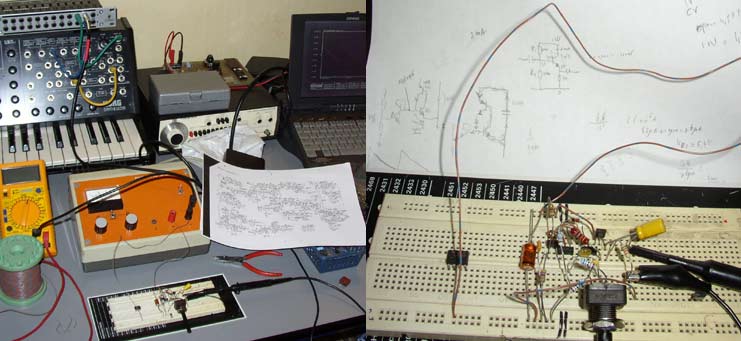
Now, it's not very nice to dig in a working machine, so i recreated a simple Korg ramp oscillator to do some tests.
And doing that i got all kinds of ideas, reading up on synthesizer electronics on internet and by dusting of some old electronic design books.
One, most notably is "Active-Filter Cookbook" by Don Lancaster. It's part of an excellent series of electronics 'cookbooks' by publisher Sams. I also have a copy
of the "CMOS Cookbook" and the "IC Op-Amp Cookbook". See for details the bottom of this page.
The "Active-Filter" cookbook covers voltage controlled filters. Like the Sallen-Key type used in the Korg.
But i first wanted to get back to get something simpler going. A Korgian ramp oscillator.
Backgrounds:
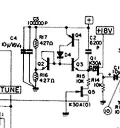
Detail from the Korg MS-20 diagram.
The current is fed to the 6200pF capacitor on the right. That's the first interesting detail; it's quite a small capacitor. The controlling current is very low.
The transistors form a sort of avalanche switch, that engages when the voltage on the bottom end goes below a set threshold. This threshold is reached in time by the it charging from the controlling current. The threshold voltage is reached at a time which is a function of the capacitance and the controlling current:
Vt = (i x t)/C
With:
Vt is the differential threshold voltage against positive rail. i is the controlling current. t is the period time of the oscillation. (Remember: Frequency = Hz = 1/t) C is the capacitance; here fixed at 6200pF.
And hence: Frequency = 1/t = (Vt x C)/i or K1/i with K1 = Vt x C; which is a fixed parameter.
In the Korg the current i is lineairly derived from the controlling voltage. This is the famous CV; control voltage. And if we state:
CV = i x K2 and K1/K2 = K
then
Frequency/CV = K [Hz/Volt]. The infamous Hz/Volt control of the Korg. Other manufacturers adopted the easier Volt/Octave; but that probably uses PLL VCO's.
Building the circuit.
In the above schedule there's some obvious rules to be distracted. Q2 and Q3 must be a closely matched pair to avoid temperature effects. I build the circuit from my collection of reclaimed old electronics parts and so i had to do a little testing to find good components.
In the end i found a pair of old 2SD636 transistors that where fast enough and matched. Q4 i chose a 2SB641. Diode a general 1N4148 type. I had a nice polypropylene 6.8nF capacitor which i used instead of the 6.2nF. For the test i did not make a current source; i just tied a resistor to ground. This was some trial and error and in the end i got 110Hz (A3 tone) by using three 560kOhm resistors in series and a 100kOhm potentiometer for some fine tuning.
And so:
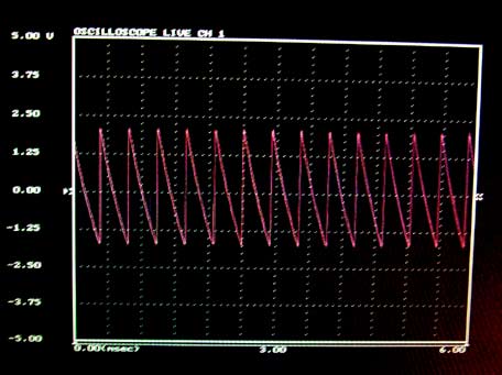
And here some scope results. The use of a resistor instead of a nice current source is obvious as the ramp is a log curve instead of a nice straight line. And there is some ringing from the FET (BS170) stage i used since i coupled the gate via a resistor instead of a wire bridge. I thought that would work, but the capacitance of the gate is clearly getting a jolt and is ringing. I only noticed it later in an audio recording. My bench oscilloscope had too little resolution.
The MS-20 has a lot of additional circuitry to make alternate shapes from this base ramp signal. Like the triangle, squarewave and pulse. These i did not build; it was just the oscillator i liked to try out.
I couldn't resist to send the resulting signal through the Korg MS-20 filters via the external signal input. The result i recorded with SoundForge:
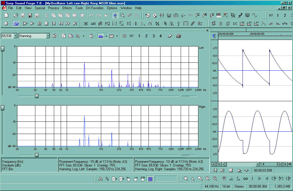
Click for enlargement...
And yes, there is also a lot of 50Hz line frequency components in the signal! It wasn't shielded at all. In fact, one could modulate the signal by simply touching the circuit, creating all kind of intermodulation products.
And here is the result in a WAV file (1.4 Mb). Sorry, an MP3 was not possible; try it, MP3 just can't compress a ramp signal!! The file has the original signal in the left channel and the MS-20 filtered version in the right.
Conclusion is really simple.. This is fun! And it calls for more!References.
The Korg company website.
Korg MS-20 Service Manual on www.korganalogue.net.
Korg MS-20 on Wikipedia
Active-Filter Cookbook by Don Lancaster; Howard W. Sams & Company, 1988, ISBN 0-672-21168-8
For further reference i recommend:
IC Op-Amp Cookbook by Walter G. Jung; Sams/Prentice Hall, 1997, ISBN 0-13-889601-1
The brilliant www.alldatasheets.com
<back to experiments main page
poesboes 20-05-2007